Utilisation
Contents
Utilisation#
Last edited: 01 Sep 2023
Author(s): Lorenzo Galieti (TU Delft, Netherlands - Politecnico di Milano, Italy)
Tristan Merbecks (Politecnico di Milano, Italy - ETH Zurich, Switzerland)
Wen Luo (TU Delft, Netherlands - RWTH Aachen, Germany)
The thermal energy produced from the reservoir can be used in a number of different applications. For example to heat homes, offices and even greenhouses - this is particularly attractive in colder climates, where heating represents a large portion of the total energy consumption.
In the summer months, already warm climates or where there are no consumers in the vicinity of the geothermal resource, the thermal energy can instead be used to generate electricity. This can be transported more easily over long distances to consumer. Fig. 18 illustrates the direct and indirect utilisations of geothermal energy with different in-situ temperatures and other reservoir conditions.
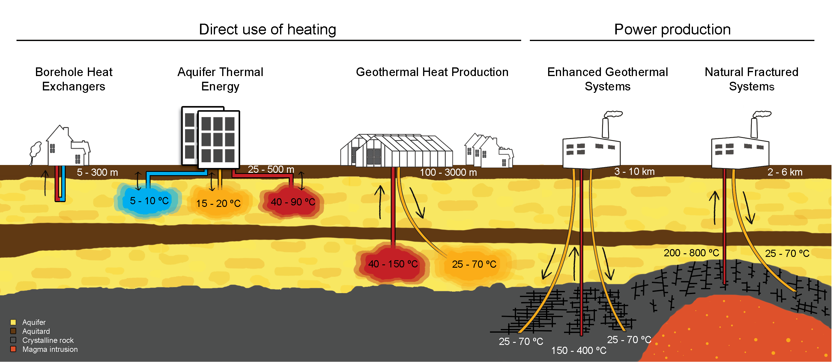
Fig. 18 The direct and indirect utilisations of geothermal energy with different in-situ temperatures. Figure provided by Martin Bloemendal [37].#
Direct Use#
The versatile direct utilisations of geothermal fluids with a temperature between 10 °C - 150 °C [38] have been ducomented for over 2000 years [39]. By the end of 2019, the total annual energy consumption from direct geothermal use is 283,580 GW h worldwide, reported in 88 countries and/or regions [40].The figure (data from [40]) below shows main categories of direct utilisations of geothermal energy, dominated by heat pumps, bathing & swimming, and space heating.
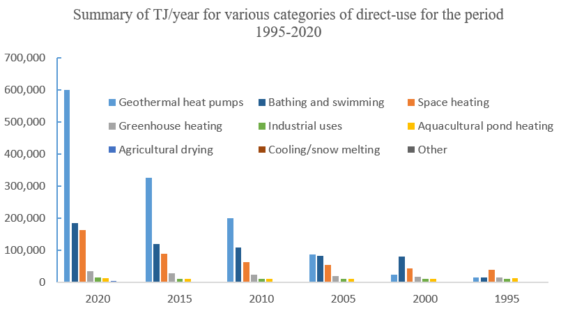
Fig. 19 The main categories of direct utilisations of geothermal energy by year.#
So far, geothermal heat pumps (GHPs), also called ground-source heat pumps, have been the most popular way to directly utilise geo-fluids since its first use in 1850s in Austria [8]. GHPs take advantage of the fact that a few meters below the Earth’s surface, the temperatue of the ground remains relatively constant, ranging from 7 °C - 25 °C [41]. In the winter, the ground is warmer than the air above it while, in the summer, colder. GHPs then acts like a refrigerator, transferring heat through geo-fluids for building heating, ventilation and air conditioning [8]. As an example showing how does a GHP work, aquifer thermal energy storage system is illustrated below.
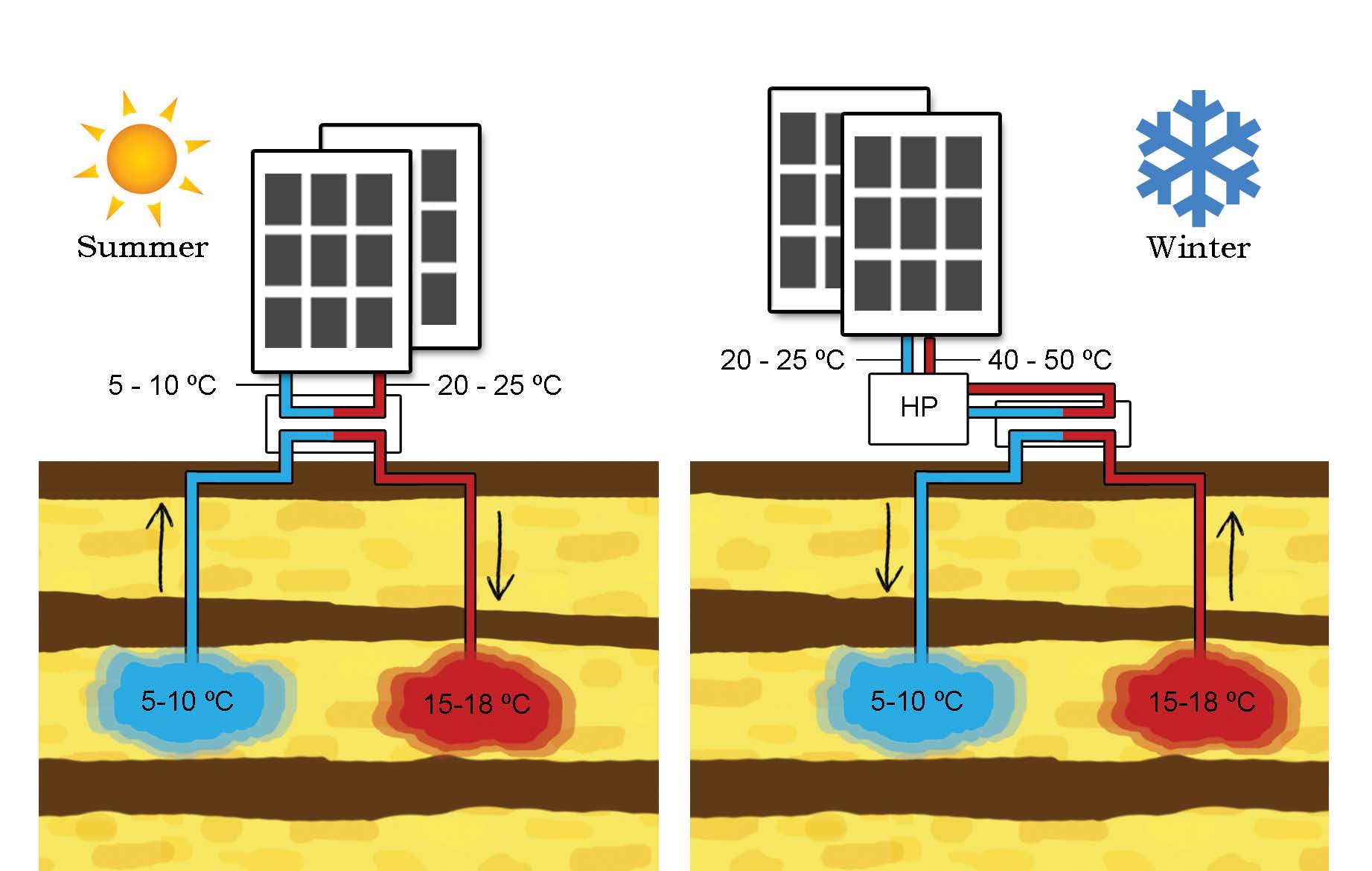
Fig. 20 Schematics of a GHP and ATES system. In the summer, water with temperature from 5 ° C to 10 ° C is extracted to cool the buldings down and the heated water with temperature from 15 ° C to 18 ° C is reinjected into the shallow subsurface. Vice visa, in the winter, water with temperature from 15 °C to 18 ° C is extracted to warm the building with the help of heat pumps, and cooled water is reinjected. Figure provided by Martin Bloemendal [37]#
Space heating, including individual space heating and district heating, dates back from 14th century when inhabitants of French village, Chaudes-Aigues Cnatal, utilised geothermal heat via a district heating networks that is still in use today [42]. Wells or multiple wells, consisting of producer and injector, are used to circulate geo-fluids with a temperature ranging from 60 °C - 90 °C [43]. If high enough temperature can be reached at a depth of 20 m - 200 m, downhole exchangers can also be used. The leading countries in space heating are China, Iceland and Turkey, with a worldwide installed capacity reaching 12768 MWt by the end of 2019 [40].
There are also many other direct applications for geothermal heat, such as:
Bathing & Swimming
Greenhouse heating
Industrial Use
Aquacultural pond heating
Agricultural drying
Snow Melting
Air conditioning
etc.
Power Plants#
Geothermal power plants convert the thermal energy extracted from the subsurface into electricity. The working principle behind converting the thermal energy to mechanical work (i.e. rotational energy) is not too different from other power plants types like coal-fired or nuclear plants.
Working Principle: The Rankine Cycle#
The Rankine Cycle is a heat engine, that converts thermal energy into mechanical work, which in turn can be used for driving a turbine. It is based on the theoretical Carnot Cycle, with adaptations to make the expansion and compression stages easier to implement with existing turbomachinery (i.e. turbines, pumps and compressors, see below).

Fig. 21 Schematic of a typical Rankine cycle power plant#
Initial State: The cycle working fluid (e.g. water) is at a low pressure and saturated liquid state
Stage 1: A pump is used to compress and pressurise the working fluid to a high pressure
Stage 2: Heat is added to the fluid at constant pressure, raising its temperature until it reaches the boiling point. From hereon, heat addition results in subsequent vaporisation of the working fluid until it is fully vapourised.
Stage 3: The high pressure vapour is expanded in a turbine, which converts the fluid’s thermal energy into rotational energy, and in turn drives a generator to produce electricity.
Stage 4: The expanded low pressure vapour is cooled at constant pressure until it reaches its condensation point. From hereon, removal of heat results of subsequent condensation of the working fluid vapour until it is fully liquefied. This returns the fluid to its initial state and closes the cycle.
Repeat from Stage 1
Depending on the temperature and physical state (i.e. vapour, liquid or a mixture of the two) of the geofluid arriving at surface, different types of geothermal power plants are:
Dry Steam#
Dry Steam power plants operate on the hottest geothermal resources, where the geofluid arrives at the surface as steam at temperatures as high as 250 °C.

Fig. 22 Schematic of a dry steam geothermal power plant#
Initial State: High-pressure saturated steam arrives at the power plant
Stage 1: The hot vapour is expanded in a turbine
Stage 2: The low-pressure vapour is condensed (e.g. using a cooling tower)
Stage 3: The low-pressure liquid is re-pressurised using a pump and re-injected into the reservoir
There are some peculiarities compared to the Rankine Cycle we discussed earlier:
The stages do not close the loop - this is because the heating and re-boiling actually takes place in the geothermal reservoir and this not usually included in the diagram
The cooling tower “loses” a considerable amount of geofluid - the typical white clouds over a power station.
This is also the reason why they are typically referred as being open-loop
Flash#
Flash power plants operate on geothermal resources, where the geofluid arrives at surface as a steam-water mixture.

Fig. 23 Schematic of a flash geothermal power plant#
Initial State: Hot high-pressure two-phase geofluid arrives at the power plant
Stage 1: The geofluid is “flashed” (i.e. reducing its pressure). This causes the fluid to partition into a liquid and vapour phase, see dashed lines.
Hint
Flashing the geofluid more can produce more steam (good) but comes at the cost of lower specific power generated by the turbine (bad) as the pressure difference across the turbine is reduced. The design engineers optimise the flashing to maximise overall power production.
Stage 2: The hot and high-pressure vapour is exanded in a turbine
Stage 3: The low-pressure vapour is condensed (e.g. using a Cooling Tower)
Stage 4: The low pressure liquid is re-pressurised using a pump and re-injected into the reservoir alongside the liquid obtained from Stage 1
Similarly to the Dry Steam plant, Flash plants are also considered “open loop”.
Binary#
Historically speaking, the first geothermal resources that were exploited were those providing brine at high temperatures, sometimes even in vapor state, as it is the case of Larderello in Italy. On the contrary, extracting energy from brines at lower temperatures is more challenging and the classical dry steam or flash power plant might not be profitable. In this case, the usual approach is to first use the geothermal brine to heat another secondary fluid, and then have this fluid undergo a rankine cycle. The cooled down brine is subsequently reinjected into the ground. This is the concept of Binary Geothermal Power Plant.
The standard rankine cycle for geothermal applications is called Organic Rankine Cycle (ORC): this is because the fluid flowing inside the machinery (pump, heat exchangers, turbine) is usually an hydrocarbon, whose properties are selected to maximize the efficiency of the power plant. In particular, the boiling point is much lower than that of compressed water, allowing the generation of the vapor that drives the turbine without any need of a flashing procedure. Howerver, such advantages come at the cost of an increased complexity of the power plant.

Fig. 24 Schematic of a binary ORC geothermal power plant#
Initial State: Hot geofluid arrives at the power plant
Stage 1: The cold low-pressure cycle working fluid is pressurised using a pump.
Stage 2: The hot geofluid heats and evaporates the cycle working fluid. The now cold geofluid is re-injected into the reservoir
Stage 3: The hot and high-pressure vapour is exanded in a turbine.
Stage 4: The low-pressure vapour is condensed
Repeat from Stage 1
Energy Conversion#
Converting between different forms of energy in reality is always associated with losses - the most common type of losses we experience in our everyday life is friction. For example, the friction between a wheel and the road surface with eventually bring the wheel to a stop. Such losses are broadly categorised as mechanical losses.
However, converting from thermal energy to more useful forms like rotational energy is more complicated. Mechanical losses could be eliminated by making the road surface smooth and frictionless, but for heat engines it is the conversion process itself that introduces losses because it is irreversible.
Reversible processes need but a small nudge to be reversed. Irreversible processes require a significant effort to reverse themselves. Cooking is a great example of an irreversible process; it is simple enough to fry an egg, but is it significantly more difficult to “unfry” the egg and return it to its original state.
Idealised Cycles#
Besides the Rankine Cycle there are a number of other “power cycles” or “heat engines” that have been proposed. The most important of these is the Carnot Cycle; it is a theoretical heat engine for converting the heat flux between two reservoirs into mechanical energy. The Carnot Cycle provides a useful upper bound for the conversion efficiency of any heat engine.
Definition: Reservoir
In the thermodynamic sense, a reservoir is a body at constant temperature - no adding or removing of thermal energy will change its temperature. An imperfect real world example of this would be a lake, to which we add a droplet of hot water.
The basic setup of a Carnot heat engine is as follows: A piston chamber is placed between two thermal reservoirs, one hot and one cold. The piston chamber walls do not permit heat or mass transfer, but one side at a time can be “opened” to allow heat transfer with the adjacent reservoir. A fluid is contained within the piston chamber.
Fig. 25 Operating principle of a Carnot heat engine#
Initial State: The walls are closed to heat transfer and the fluid in the piston chamber is at the same temperature as the hot reservoir, THot
Stage 1: The wall in contact with the hot reservoir is opened to allow heat transfer. The piston is then slowly raised, increasing the volume of chamber. Meanwhile, the temperature of the cell remains at THot as heat moves from the hot reservoir into the cell. This is also referred to as isothermal heat addition
Stage 2: The chamber is once again isolated from the two reservoirs. The piston is then raised, increasing the volume of the chamber until the fluid cools to the temperature of the cold reservoir, TCold. This is referred to as isentropic expansion
Stage 3: The wall in contact with the cold reservoir is now opened to allow heat transfer. The piston is then slowly pushed down, reducing the volume of the chamber. The temperature in the cell remains at TCold, as the heat moves from the chamber into the cold reservoir. This is referred to as isothermal heat removal
Stage 4: The chamber is again isolated and then the piston is pushed down, reducing the volume until the temperature reaches that of the hot reservoir THot. This is referred to as isentropic heat removal
Repeat from Stage 1
So, how does this generate work? Looking at the Temperature-Entropy (TS) diagram, we can see that we put in a lot more heat than we remove (i.e. Qin vs. Qout). However as this is a cyclic process, and the fluid returns to its original state, there is no accumulation of energy in the system. Hence, it follows that the difference is the net work done.

Fig. 26 Temperature-Entropy diagram of a Carnot heat engine#
The heat added to the fluid is given by: \(Q_{in} = T_{Hot} * (S_2 - S_1)\)
The heat removed from the fluid is given by: \(Q_{out} = T_{Cold} * (S_2 - S_1)\)
Hence, the net work done is given by: \(W_{Net} = Q_{in} - Q_{out}\)
The conversion efficiency is thus: \(\eta = \frac{W_{net}}{Q_{in}} = \frac{(Q_{in} - Q_{out})}{Q_{in}} = 1 - \frac{T_{Cold}}{T_{Hot}}\)
The Carnot Cycle represents the ideal heat engine, meaning it most efficiently converts thermal energy into work. Unfortunately, translating this conceptual cycle into a real-life heat engine is challenging and so far we lack the equipment to make all stages of the cycle work.
Stage 1 and Stage 3 (i.e. isothermal heat addition/removal) are relatively easy to realise. Here, one could take a pure fluid, e.g. water, and make it undergo a phase change, for example from liquid to vapour or vice versa, as phase changes for pure fluids occur at a constant temperature.

Fig. 27 Carnot cycle with a pure cycle working fluid#
However, this makes it more difficult to realise Stage 2 and Stage 4 (i.e. isentropic expansion/compression). This is because the machinery to expand/compress fluids are designed to either work on a vapour or liquid but struggle with two-phase mixtures. For example, a pump designed to pressurise a liquid, but significant vapour fraction causes cavitation and damages the internals. Similarly, turbines are designed to expand gases and significant liquid fraction can damage the blades.
Efficiency#
The efficiency of heat engines and power plants can be investigated from different perspectives.
When we would like to know how much of the thermal energy we brought to surface has been converted into work/electricity, etc. we speak of a First Law Efficiency. This is commonly referred to as the thermal efficiency or the cycle efficiency.
Whereas when we would like to know how our heat engine compares to an ideal heat engine (e.g. the Carnot Cycle) we instead speak of a Second Law Efficiency. The Second Law Efficiency can thus come in different “flavours”, depending on what reference conditions are selected:
Utilisation Efficiency:
\[\eta_{II, utilisation} = \frac{W_{Net}}{E_{in}}\]Functional Efficiency:
\[\eta_{II, functional} = \frac{W_{Net}}{E_{in}-E_{out}}\]Utilisation Efficiency:
\[\eta_{II, cycle} = \frac{W_{Net}^{real}}{W_{net}^{ideal}}\]
Definition: Enthalpy, Entropy and Exergy
The enthalpy, H, is a measure of the amount of energy required to create a system. This includes the energy contained within the chemical species, also known as the internal energy, U, and the pressure-volume work required to create space for the system.
The entropy, S, is a measure of the amount of energy that is unavailble for conversion into work.
The exergy, E, is a measure of the maximum amount of work that can be obtained from fluid at a given temperature and pressure.
Power Plant Equipment#
Turbine#
All the geothermal power plants convert the thermal energy into electricity by using several different machinery. In particular, the most well known component is the turbine: its scope is to extract the energy of the hot vapour and convert it into mechanical power. To do so, it relies on the force generated by elements called blades, whose working principle is briefly shown in the figure below. Because of the action-reaction principle, when the blade bends the vapour flow downwards, it experiences an opposite force pushing it upwards. A similar idea is used in many other engineering applications, such as aircraft wings, Formula 1 ailerons and boat hydrofoils.

Fig. 28 Forces acting on a turbine blade. The turbine rotation is driven by the lift.#
When the blade is attached to a shaft, such force will induce a torque that will consequently drive the rotation of the turbine.

Fig. 29 Rotation of the turbine shaft#
A typical axial turbine for binary geothermal power plants is shown below (courtesy of Turboden).
Pump#
The working principle of pumps in use in binary geothermal power plants is very similar to the one governing the rotation of the turbine. It once again relies on the lift generated by the blades. This time however, instead of allowing the lift drive the rotation, as it is done in the turbines, the machine is forced to rotate against such lift instead, thereby transferring energy to the fluid and increasing its pressure.

Fig. 30 Pump working principle: the blade elements generate a lift just as in the turbine, but in this case, the pump rotates against the lift.#
Heat Exchangers#
The heat exchangers come in different models and are responsible for several different thermodynamic transformations. We can usually distinguish between two different types of heat exchangers: the fin and tube heat exchangers and the shell and tube heat exchangers.
The first ones, as the name says, employ finned tubes to promote the heat exchange. They are required when there is one fluid in gaseous phase participating to the heat exchange process: this is because, normally, the tendency of a gas to exchange heat is quite low.
Fin and Tube Heat Exchangers#
A typical example of a finned tube is shown below: the gas flows outside the finned tube in a direction perpendicular to the plane of the image, and makes use of the increased heat exchange area provided by the fins to compensate for its low tendency to exchange heat. The other fluid flows instead inside the tube. This second fluid has to be either liquid or evaporating/condensating, and can be gaseous only for small portions of the heat exchanger. Instead, heat exchangers which allow two gases to exchange heat are of a different kind, but are usually not necessary in geothermal applications.

Fig. 31 Example of a finned tube#
Fin and tube heat exchangers are usually used in two different cases: either when the binary power plant uses a regenerator or if the the condenser is air-cooled. Such air-cooled condensers are usually very large, and in some cases constitute the only visible component of the power plant. One of this examples is shown below (courtesy of Turboden).
They are constituted by a series of fans drawing air from the bottom of the heat exchanger and pushing it against the finned tubes containing the condensing fluid. The fans can consume a significant portion of the power plant power output and, for this reason, when water cooling is available it is generally much preferrable. However, in remote locations this is usually not a possibility.

Fig. 32 Schematic of an air cooled condenser#
Shell and Tube Heat Exchangers#
The shell and tube heat exchangers can instead be utilized when there is little fluid in gaseous phase contributing to the heat exchange process: their typical application is in the evaporator of the binary power plant, which is responsible of transferring heat from the geothermal brine to the working fluid undergoing the rankine cycle. Here, usually two different shell and tube heat exchangers are used: one to preheat the fluid and bring it on the verge of evaporation, and the other to promote the evaporation and eventually provide vapor to the turbine. In addition, they are convenient if the condenser can be water-cooled.
The figure below shows the most classic type of shell and tube heat exchanger. It finds its use everywhere in the power plant, except (normally) when boiling the working fluid of the ranking cycle. Its principle of operation is as follows: one of the fluids flows straight inside the tubes, while the other one goes through the serpentine path in the shell. As also the tubes are inserted in the shell, the two fluids can exchange heat.

Fig. 33 Schematic of a shell and tube heat exchanger#
When instead the rankine cycle fluid needs to be boiled after preheating, a special type of shell and tube heat exchanger, called kettle reboiler, is used. The shell of the heat exchanger in this case works like a cooking pot, that contains the rankine cycle fluid that needs to be boiled. However, in contrast to the pot, heat is not provided from below by a flame, but rather from the geofluid itself, that flows inside the tubes inserted in the shell. Once vapour is generated, it tends to go upwards, were it will exit the heat exchanger. On the right, a little bit of space is left between the wall delimiting the tubes (and, thus, the evaporation zone) and the shell. This is done to allow such wall to rotate, so as to control the boiling fluid level in the heat exchanger. This in turn is one of the mechanisms to control the power plant.

Fig. 34 Schematic of a kettle reboiler#
Cooling Tower#
In flash power plants the geofluid is usually condensed downstream of the tubine, by means of a machine called cooling tower. From the outside, this device appears as a conical tower, as shown in the figure below. The geofluid is sprayed by nozzles and part of it evaporates into the air raising from the bottom of the tower. The remaining part falls down, where it is collected and injected back into the reservoir.

Fig. 35 Schematic of a cooling tower#
The principle if very similar to what happens when we mix too much sugar into coffee: some of it will dissolve in the liquid, giving it a sweeter taste, the rest will fall to the bottom of the cup. Nature tells us the process requires heat, hence the geofluid falling to the bottom of the tower will also cool down.